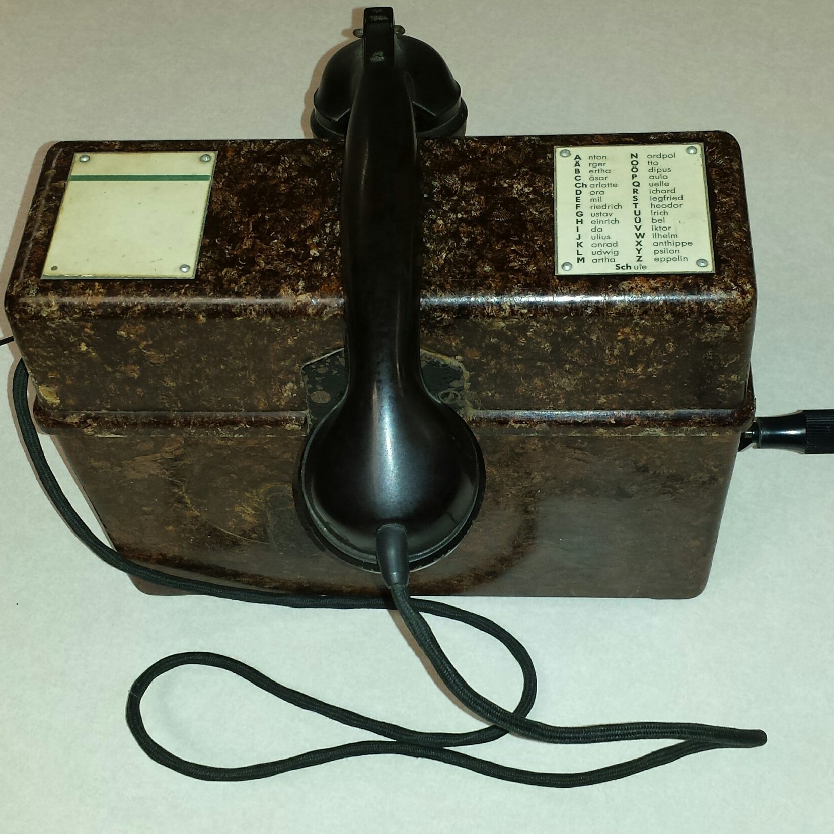
In Part 1, I talked about the basic features of the Vermittlungskästchen module, and how two or more modules are usually latched together mechanically and electrically. Now, let’s see how the Vermittlungskästchen operates.
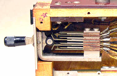
The heart of the Vermittlungskästchen is a Kellogg Switch. This switch mechanically changes the state of 8 electrical contacts within the Vermittlungskästchen box.
Consider the electrical schematic below…
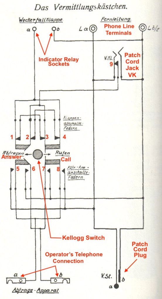
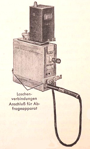
Suppose three modules are latched together. Each module is connected to an OB field telephone line. These are Line 1, Line 2, and Line 3.
When a call comes in on the La and Lb/E terminals of Line 2, the indicator relay (Weckerfallklappe) energizes, and a yellow flag appears in the relay’s window. The operator acknowledges the call by resetting the relay and moving the Kellogg Switch on Line 2’s module from the neutral position down to the answer (Abfragen) position.
In the answer position, contacts 5 and 6 are closed, connecting the operator’s telephone to the Vermittlungskästchen. There is a detent on the switch, so it will stay in the answer position until it is moved back to the neutral position. The operator can now talk to the caller. The caller on Line 2 wants to talk to the party on Line 1.
The operator puts the Line 2 switch back to the neutral position to place the caller on hold. This opens contacts 5 and 6. The operator the presses the switch to call (Rufen) position on Line 1 while turning the crank on his field telephone. He has to hold the switch button in the call position while turning the crank, because the switch has no detent. Contacts 7 and 8 close, and the phone on Line 1 rings.
The operator the returns the switch on Line 1’s module back to the neutral position, removes the patch cord of Line 2’s module from the RK socket. He then inserts Line 2’s patch cord plug into Line 1’s VK jack socket. Line 1 is now connected to Line 2.
Now, when the switch is in the answer or call positions, contacts 1, 2, 3, and 4 are opened. This disables the indicator relay. The relay is also disabled via contact 9 when a patch cord plug is inserted into the VK jack. The relay is only enabled when the switch is in the neutral position and there is no plug in the VK jack.
It’s interesting to note that, regardless of whether the switch is in the answer or call positions, the operator’s phone is connected to the line via contacts 5 and 6 or 7 and 8. This means that the operator can talk on or call a line with the switch in the answer position. In other words, the call position is not really needed.
In Part 3 we’ll talk about adding an optional speaker or headphone plus single wire versus double wire connections.
For more information about modular switchboards, and field switchboards in general, check out my book: https://www.lulu.com/en/us/shop/rotwang-manteuffel/world-war-2-german-field-telephone-equipment-a-basic-guide-for-reenactors-and-historians/paperback/product-976w9q.html?page=1&pageSize=4