The voice transformer isolates the battery powered microphone circuit from the speaker circuit. The transformer also amplifies the voice signal produced by the microphone. The transformer is located in the FF33, for example, above the magneto.

The transformer is held to the telephone frame by two screws.

The transformer has four windings (coils), I, II, III, and IV. On the winding covering, each coil is identified as follows: I: 3.5/370/0.28 CuL; II: 30/1600/0.24 CuL; III: 108/800/0.10 CuL; IV: 300/bif/0.10 WdSS. Coil I is the primary coil and coils II, III, and IV are the secondary coils. The first number is the coil resistance in ohms. For coils I, II, and III, the second number is the number of turns, and the third number is the wire diameter and wire material. Coil IV is a special coil made from resistance wire, and the second number is the wire type, where “bif” is an abbreviation for “bifilar.” “WdSS” is an abbreviation for “braided twice with silk.”


Inside the lid of the FF33, a schematic of the telephone is furnished. In the schematic, the voice transformer is denoted by “J.”

When switch “T” is closed in the handset, the microphone “M” receives power from the 1.5 volt battery “MB.” Voice signals are transmitted trough 3.5 ohm transformer coil I. The voice signals are inducted through the transformer to coils II, III, and IV. These coils have a resistance of 30, 108, and 300 ohms respectively. The voice signals then leave the transformer and travel to the other connected telephone.
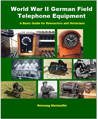
Check out my new book on WW2 German field telephone equipment…https://www.lulu.com/en/us/shop/rotwang-manteuffel/world-war-2-german-field-telephone-equipment-a-basic-guide-for-reenactors-and-historians/paperback/product-976w9q.html?page=1&pageSize=4